Wiring To The Track
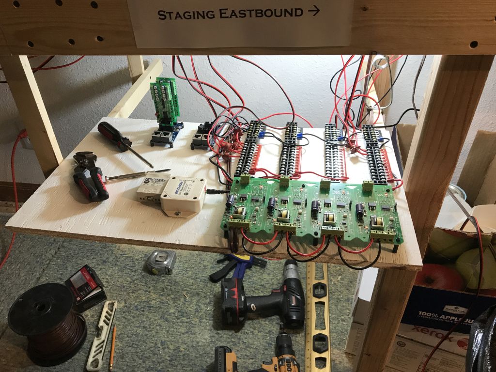
A few have asked how I wire out the blocks with the LCC system. On my last layout expansion, I put all the electronics under the layout. This resulted in a lot of hours working kinda sitting up leaning back while working overhead. Never liked it and was undesirable. On this buildout, I tried to minimize the amount of work under the layout and directed ALL my wiring to pull-out shelves at strategic locations. Here is a pic of one of those shelves. As you can see, it’s nothing fancy – just 1/2” plywood on a frame of 1x2 slides.

The only thing I would do different is In the pic, I show the BOD-8’s plugged into the Tower-LCC; instead I would mount those separately with a 10-conductor cable jumper between.
Power comes from the breakers in the lower right, up to the TBs in the upper right. Then from the TBs, pairs of wire go out to the blocks. One wire on the wire pair goes through CT (barely visible in the upper center of the photo).
The only work under the layout is where I tap off track feeders to each section of track for each block. I have come to use and like IDE connectors, a.k.a., “suitcase connectors.” The do all the connections in one crimp, again minimizing time under the layout. Here is a pic of three pair of track feeders off the block feeder. (the third pair of IDE connectors is hidden behind two of them)

A note about power feeder sizes. I probably will get sneers from saying this, but I ran 14AWG from the boosters to the TBs, then 16AWG from the TBs to the blocks; 22 AWG track feeders. I like running 2-3 diesel MU trains and have not had any issues. Think about it this way: 16AWG will have something like 10% voltage drop across 15' at 5A. 5A of locomotives is pretty serious. Say I have 3 units at maybe 1/2A each... so 1.5A across 15' in 16 AWG, my v-drop calculator shows 0.18V drop, or 1.29%. I just don't see the need to put more money into copper if that is all that will happen. Even if I double it, 3A across 15' in 16AWG will have 2.5% v-drop or 0.36V. Like I say, some will say run at least 12AWG or 14 AWG from the boosters, and then use 14AWG for the bus leads. Very nice and robust. I just cannot justify it. The 22 AWG leads up to the track (of which I have at least 2 pair, sometimes 3-4 pair), is very small and makes for an almost invisible track connection.


Greetings Detlef,
ReplyDeleteI'm slooowly moving forward in my understanding of LCC. I thought I read somewhere that you successfully had physical push button (SPST?) and LEDs to your Tower LCC, BOD-8, SMD-8 configuration. If so, do you have any wiring diagrams you could share? I'm finding my weak electronics background to be a hindrance.
Thanks,
Kent
Yes I do! And in fact, I have all the screen shots and steps ready to put together into a blog post. This little feature is exactly why I went with LCC: I can run the layout with local push buttons when I don't have the PC on, or I can run it via the PC when I have formal op sessions. LCC perfectly allows and is designed for this!
DeleteSo I just need to find a free couple of hours to put it all together. Stay tuned!