Configuring Push-buttons for Turnout Control in LCC (with BONUS section on Adapting JMRI for Feedback)
So ALL the efforts, costs, brain damage and such to get LCC integrated into the layout is paying off in this one new step. Let me explain.
With LCC, each node is essentially its very own stand-alone microprocessor, capable of processing commands INDEPENDENTLY of a central PC or other server. It just is connected to at the CAN bus, either looking for commands to respond (consumer) to or to issue them (producer). SO... this addresses one of the goals of integrating LCC into my layout. Sometimes I like to come down into the layout room and just run trains. I don't have others with me, and for me, its a great way to unwind. When I do that, I don't want to have to futz with turning on a PC and getting it going. Ya, I know, some say it is not that big of a deal. But if I am only going to be there for 5 or 15 minutes, seems like a hassle to mess with that. I just want to through the power switch on, have the layout come to life, and run some trains. Other times, I enjoy hosting op sessions. I have a separate room for the DS (dispatcher), and I would like all the track controls run from the computer.
All this to say that I finally am to the point where I am adding push button controls for the LCC controlled switches. This blog post shows HOW to wire the PBs into LCC, as well as configuring that I/O to throw the switches. In this process, I discovered that I needed to modify my JMRI PanelPro panel to read the LCC status of the turnouts instead of following its own status. More on that later.
STEP 1 - WIRING IN THE PUSH BUTTONS
Recall both the Tower-LCC and Signal-LCC have I/O set up to allow them to either be an output or an input. For the push buttons, we will need to set them up as inputs. Dick Bronson and team very cleverly designed the boards to be set up to provide both the interrogation voltage for the PBs as well as provide "pull up" resistors to avoid spurious input data. Each input is NORMALLY HI, that is, at 5V. The input pins need to be GROUNDED to "turn on." Again, RR-Cirkits conveniently provides +5 and Ground on their 10 pin connectors. So for example, if I wanted to connect a push button onto line 1 below, I just need to wire as shown.

The panel I built is for local operation of the "dispatcher controlled" turnouts within my main yard. During op sessions, the yard operator should not need to use this panel. As I mentioned, when it's just me, I do want local control. So without a lot of fanciness, I put together a very simple panel (maybe some day I'll make it nicer). White painted masonite; 1/4" holes, Sharpie marker and it was ready for installation of the PBs! For wiring, I just jumpered the ground lead to each PB, and then each of the input line wires to each PB. Note that I bought a spool of the ribbon cable recommended for connection to the RR-Cirkits products, including extra 10-pin connectors. This makes wiring to the node very easy.
Once the panel was ready to go, I brought it over to the layout and threaded the ribbon cable between the panel location and the Signal-LCC.


STEP 2 - CONFIGURING INPUTS FOR PUSH BUTTONS
Now go back to your PC and open up PanelPro. I wont rehash how to get to the screen where you configure the nodes; look at a previous blog post to find that.
Like before, first thing is the name the node. I just named it local control panel:

Next start configuring the lines as inputs. Recall the inputs are NORMALLY (not active) in the HI condition. So when pushing the PB, the input goes LOW....
Now go to the producers section and configure Event 1 and 2. Event 1 is when the button gets pushed; Event 2 is when it gets released. So there are 2 events produced when the PB gets pushed once.


Note those event names, we will use them shortly.
Anyway, at this point the PBs are configured! Congrats! If you power up your LCC network, you will see lights blink whenever you push and release a PB. Of course, we have not configured anything to respond to those commands, so nothing happens. The buttons are just producing events. So on to Step 3.
STEP 3 - CONFIGURING THE TURNOUT DRIVER TO RESPOND TO THE PB EVENTS
I got all balled up trying to noodle logic on how to have a single event change the control of a turnout. Once again, the good folks at RR-Cirkits are WAY ahead of me and have this all figured out.. and easily implemented.
Go to the turnout driver that you want to respond to the PB event:

Scroll down to the Consumer section... and look at the tab for EVENT 3:

Check it out: there is the option for TOGGLING the state! So just copy-paste the producer you want to trigger the change, and select CHANGE (TOGGLE) for what the command should do. Wa--LA! Done!
Go back to your push buttons and enjoy your new control. It really is that easy. Again, note that at this point YOU DON'T NEED THE PC ANYMORE. Turn it all the way off if you like. That PB will run that turnout without any external command or control interface. I just love this.
ALSO note that I could put as many PBs around the layout as I want to drive this turnout. That means turnout controls from opposite sides of the aisle. Or perhaps at a staging yard. And speaking of staging yard, you could have a single PB align MULTIPLE turnouts to a specific position. Cool, huh?
OK, all this went well until I went back to my PC and I wanted to see the turnout throw when pushed from the PB. Well, that did not work. JMRI was only looking at the JMRI command to ID position, so it never knew that the LCC network did its own thing. Some help from the amazing people on the Layout Command Control forum provided the answer.
STEP 4: CONFIGURING JMRI TO MONITOR LCC TURNOUT POSITION FEEDBACK
This was by no means intuitive, but it makes all the sense in the world once I did it.
1: Go back to the LCC TURNOUT PRODUCER FIELD:

2. Change to OUTPUT ON. This will PRODUCE an LCC event when the turnout is moved into both the closed and thrown position. Need to do this for both positions; Event 1 and Event 2.


3: Create a name for this new signal. I prefixed with "FB" for "Feedback."

4. Now create a JMRI Sensor for this signal, just like before.

5. Go to the TURNOUT TABLE in PanelPro and find the turnout this feedback is associated with and click on EDIT:


With LCC, each node is essentially its very own stand-alone microprocessor, capable of processing commands INDEPENDENTLY of a central PC or other server. It just is connected to at the CAN bus, either looking for commands to respond (consumer) to or to issue them (producer). SO... this addresses one of the goals of integrating LCC into my layout. Sometimes I like to come down into the layout room and just run trains. I don't have others with me, and for me, its a great way to unwind. When I do that, I don't want to have to futz with turning on a PC and getting it going. Ya, I know, some say it is not that big of a deal. But if I am only going to be there for 5 or 15 minutes, seems like a hassle to mess with that. I just want to through the power switch on, have the layout come to life, and run some trains. Other times, I enjoy hosting op sessions. I have a separate room for the DS (dispatcher), and I would like all the track controls run from the computer.
All this to say that I finally am to the point where I am adding push button controls for the LCC controlled switches. This blog post shows HOW to wire the PBs into LCC, as well as configuring that I/O to throw the switches. In this process, I discovered that I needed to modify my JMRI PanelPro panel to read the LCC status of the turnouts instead of following its own status. More on that later.
STEP 1 - WIRING IN THE PUSH BUTTONS
Recall both the Tower-LCC and Signal-LCC have I/O set up to allow them to either be an output or an input. For the push buttons, we will need to set them up as inputs. Dick Bronson and team very cleverly designed the boards to be set up to provide both the interrogation voltage for the PBs as well as provide "pull up" resistors to avoid spurious input data. Each input is NORMALLY HI, that is, at 5V. The input pins need to be GROUNDED to "turn on." Again, RR-Cirkits conveniently provides +5 and Ground on their 10 pin connectors. So for example, if I wanted to connect a push button onto line 1 below, I just need to wire as shown.

The panel I built is for local operation of the "dispatcher controlled" turnouts within my main yard. During op sessions, the yard operator should not need to use this panel. As I mentioned, when it's just me, I do want local control. So without a lot of fanciness, I put together a very simple panel (maybe some day I'll make it nicer). White painted masonite; 1/4" holes, Sharpie marker and it was ready for installation of the PBs! For wiring, I just jumpered the ground lead to each PB, and then each of the input line wires to each PB. Note that I bought a spool of the ribbon cable recommended for connection to the RR-Cirkits products, including extra 10-pin connectors. This makes wiring to the node very easy.
 |
| Ground is jumpered between PBs |
 |
| Started adding leads from ribbon cable. |
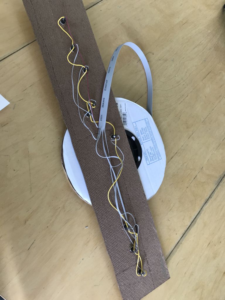 |
| Finished wiring, ready to run lead back to Signal-LCC. |
 |
| Nothing fancy, that is for sure! |
Once the panel was ready to go, I brought it over to the layout and threaded the ribbon cable between the panel location and the Signal-LCC.

Once threaded through, I attached the 10-pin connector and DONE! It really went fast. Note: it is very important to correctly attach the connector to keep the wiring to the right pins. The tracer (wire 1) goes to Line 8.

STEP 2 - CONFIGURING INPUTS FOR PUSH BUTTONS
Now go back to your PC and open up PanelPro. I wont rehash how to get to the screen where you configure the nodes; look at a previous blog post to find that.
Like before, first thing is the name the node. I just named it local control panel:

Next start configuring the lines as inputs. Recall the inputs are NORMALLY (not active) in the HI condition. So when pushing the PB, the input goes LOW....
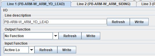 |
| Note Input Function is Active Lo. No output function. |
Now go to the producers section and configure Event 1 and 2. Event 1 is when the button gets pushed; Event 2 is when it gets released. So there are 2 events produced when the PB gets pushed once.


Note those event names, we will use them shortly.
Anyway, at this point the PBs are configured! Congrats! If you power up your LCC network, you will see lights blink whenever you push and release a PB. Of course, we have not configured anything to respond to those commands, so nothing happens. The buttons are just producing events. So on to Step 3.
STEP 3 - CONFIGURING THE TURNOUT DRIVER TO RESPOND TO THE PB EVENTS
I got all balled up trying to noodle logic on how to have a single event change the control of a turnout. Once again, the good folks at RR-Cirkits are WAY ahead of me and have this all figured out.. and easily implemented.
Go to the turnout driver that you want to respond to the PB event:

Scroll down to the Consumer section... and look at the tab for EVENT 3:

Check it out: there is the option for TOGGLING the state! So just copy-paste the producer you want to trigger the change, and select CHANGE (TOGGLE) for what the command should do. Wa--LA! Done!
Go back to your push buttons and enjoy your new control. It really is that easy. Again, note that at this point YOU DON'T NEED THE PC ANYMORE. Turn it all the way off if you like. That PB will run that turnout without any external command or control interface. I just love this.
ALSO note that I could put as many PBs around the layout as I want to drive this turnout. That means turnout controls from opposite sides of the aisle. Or perhaps at a staging yard. And speaking of staging yard, you could have a single PB align MULTIPLE turnouts to a specific position. Cool, huh?
OK, all this went well until I went back to my PC and I wanted to see the turnout throw when pushed from the PB. Well, that did not work. JMRI was only looking at the JMRI command to ID position, so it never knew that the LCC network did its own thing. Some help from the amazing people on the Layout Command Control forum provided the answer.
STEP 4: CONFIGURING JMRI TO MONITOR LCC TURNOUT POSITION FEEDBACK
This was by no means intuitive, but it makes all the sense in the world once I did it.
1: Go back to the LCC TURNOUT PRODUCER FIELD:

2. Change to OUTPUT ON. This will PRODUCE an LCC event when the turnout is moved into both the closed and thrown position. Need to do this for both positions; Event 1 and Event 2.


3: Create a name for this new signal. I prefixed with "FB" for "Feedback."

4. Now create a JMRI Sensor for this signal, just like before.
5. Go to the TURNOUT TABLE in PanelPro and find the turnout this feedback is associated with and click on EDIT:
6. Go to the FEEDBACK tab - note it shows MONITORING. (We will have to change that.)

7. Change to ONE SENSOR and link back to that feedback sensor that you created.

DONE! The panel graphic will now follow the turnout position, regardless of where the command came from, whether it be the PB or via JMRI.
Now go enjoy running those trains!

Interesting, but it all looks foreign to me. Must you use the very cryptic event IDs or can they be replaced with terms that are more meaningful? Also, if you need more ten conductor flat cable, let me know. I have some to spare.
ReplyDeleteDave Cochrun
The event ID is what is carried through the network, so that is what is referenced. Since they are so long and awkward, the software allows you to readily copy/paste the address, as well as the descriptions where needed. I know, a bit of a pain. Thanks for the offer of the flat cable. That stuff is pricey, so been using it sparingly. Alas, probably too sparingly. I have a bunch of it still. That said, signals are coming and those will consume a lot of cable, so I may be calling on you. Thanks Dave!
Delete