More on LCC - Configuring a Turnout
The blog post on configuring a node raised some eyebrows since the nodes come essentially already configured for detection. I had to configure a bunch of Tortoise stall motor drive outputs, so presenting a step-by-step for configuring those kinds of outputs.
For this post, I am using an RR-Cirkits Tower-LCC board with an RR-Cirkits SMD-8 stall motor driver board attached.
As before, everything is done via JMRI Panel Pro. Open Panel Pro and then the OpenLCB config tool:

As before, open the node and click on the Config Dialog:

You'll see the info upload from the node. This is a tower LCC with several points already configured. We will do point 11:

Click on tab Line 11 and, just as before, name the point. Note that it changes to an orange background to show it was not changed on the node:

Click on "Write" and it's in!

Now scroll down to the Producer/Consumer options. The whole discussion about producers and consumers can get a bit confusing, but the way I like to think of it is as follows:

A few things to note:


Seems about 50% of the time the turnout will throw opposite of what I need it to do. Instead of rewiring or changing anything in JMRI, I simply go back up to the Output Function configuration and change from "Steady Active Hi" to "Steady Active Lo". This effectively reverses all the logic downstream from there, and leaves everything working right.
For this post, I am using an RR-Cirkits Tower-LCC board with an RR-Cirkits SMD-8 stall motor driver board attached.
As before, everything is done via JMRI Panel Pro. Open Panel Pro and then the OpenLCB config tool:

As before, open the node and click on the Config Dialog:

You'll see the info upload from the node. This is a tower LCC with several points already configured. We will do point 11:

Click on tab Line 11 and, just as before, name the point. Note that it changes to an orange background to show it was not changed on the node:

Click on "Write" and it's in!

Now scroll down to the Producer/Consumer options. The whole discussion about producers and consumers can get a bit confusing, but the way I like to think of it is as follows:
- A PRODUCER receives information FROM the layout to PRODUCE a signal on the LCC network. And...
- A CONSUMER received information FROM the LCC network to PRODUCE an output TO the layout.
Since the Tower-LCC is by default set up to use the I/O points to produce indications, that is be a producer, we need to change that to make them be consumers. This will let them get signals from the LCC network and output a signal to the layout, specifically to the stall motors.
Here we go:
Scroll down to the Input/Output section:

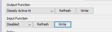
Here we see that the default set up is to OUTPUT is shut off (No Function) and the input from the layout is designed to be "on" when the input is "low." This matches the BOD-8 requirements. We want it to be an output, however, so change the Output Function to be "Steady Active Hi" and disable the input function.

Note: the Input Function HAS to be disabled. Input has priority over output, and if it is not disabled, you will not see any output functionality. (Ask me how I know...)
Be sure to hit "Write" on each change. Just changing the function on the pull-down menu won't write it to the node.
OK, now we need to define how those outputs are configured.
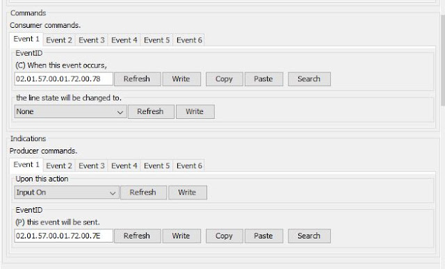
Scroll down to the Producer/Consumer section and define the actions you want when an event happens:
- For the consumer events, note that by default the Event will trigger no action. See the description that says, "...the line state will be changed to [None]." That won't do anything for us! So we need to change that for Event 1 and Event to "Active" and "Inactive" respectively.
- You don't need to do anything with Producer commands. Because we told the node up top to disable the producer functions, you can leave this section as is.
So changing Event 1 looks like this now:

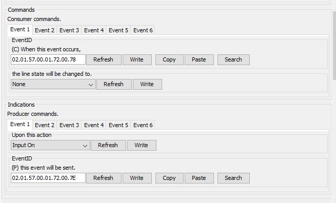
Do similar for Event 2:

Note that if you make Event 1 and Event 2 do the same thing, the turnout will stay in the same position regardless of if the control signal tells it to throw. Ask me how I know...
OK, that's it! You have now configured a node to operate turnouts. Pretty easy, eh?
------------------------------------------------------
Like before, here are a few more steps needed to upload this into a JMRI panel.
First thing is to open Panel Pro and open the panel. That HAS to be open. Then open the Turnout Table. And as before, open the Sensor/Turnout Creation tool: (This little tool is AWESOME! Thanks to the team at RR-Cirkits for including this little gem!)

Now name the point (I used the same name as the point); copy and paste in the event ID's for Events for thrown and closed and click on Make Turnout:

Done! The turnout should have shown up in your Turnout Table. Now you can use it on your panel.

Hope this was helpful. Feel free to post q's if you have any.


Just found this post as I embarked on configuring my first 8 turnouts in LCC/JMRI using an SMD-8, very helpful as I cannot seem to find this type of documentation elsewhere!
ReplyDeleteThanks. That is what I discovered as well, which is why I put this together. Working on a YouTube channel with similar info (The LCC Channel): https://www.youtube.com/channel/UCuRRF7W2tX4UjFhDAontT4Q
Delete