Posts

Showing posts with the label Tower-LCC

LCC - Configuring a Push Button ~WITH~ Indication

Image
A few months ago there was a post on the LCC Groups.IO forum talking about the ability for one of the LCC node I/O points to both act as an INPUT, that is, to accept a push button command, AND act as an output, such as to illuminate an indicating light.  This is super cool!  Why?  Well at an all-in cost of around $3 per I/O point, it's hard to justify a lot of indicating lights on panels.  BUT... if we can get a "free" output for each discrete input, well, that is just like having your cake and eating it too!  (Never totally understood that analogy, but seems fitting.) The way this works is the node runs the I/O point as an output for 63 milliseconds, and then for a few milliseconds, it converts the output to an input where it polls the input.  So if it detects a "low" or a "high" in this window, it creates the appropriate event.  Slick, huh?  Timing at 63 ms is fast enough that even if the PB is just momentarily touched, it is enough to trigger...

Configuring Push-buttons for Turnout Control in LCC (with BONUS section on Adapting JMRI for Feedback)

Image
So ALL the efforts, costs, brain damage and such to get LCC integrated into the layout is paying off in this one new step.  Let me explain. With LCC, each node is essentially its very own stand-alone microprocessor, capable of processing commands INDEPENDENTLY of a central PC or other server.  It just is connected to at the CAN bus, either looking for commands to respond (consumer) to or to issue them (producer).  SO... this addresses one of the goals of integrating LCC into my layout.  Sometimes I like to come down into the layout room and just run trains.  I don't have others with me, and for me, its a great way to unwind.  When I do that, I don't want to have to futz with turning on a PC and getting it going.  Ya, I know, some say it is not that big of a deal.  But if I am only going to be there for 5 or 15 minutes, seems like a hassle to mess with that.  I just want to through the power switch on, have the layout come to life, and run s...

Wiring To The Track

Image
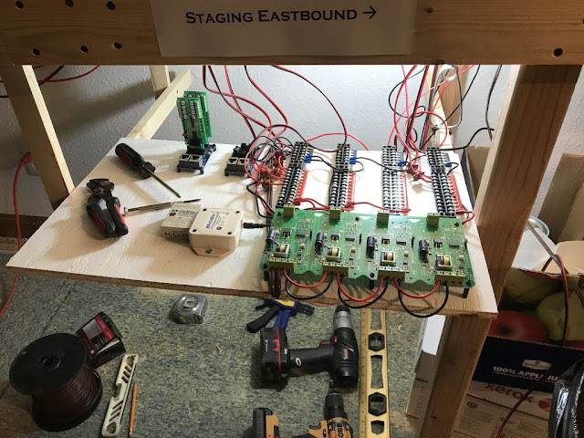
A few have asked how I wire out the blocks with the LCC system.  On my last layout expansion, I put all the electronics under the layout.  This resulted in a lot of hours working kinda sitting up leaning back while working overhead.  Never liked it and was undesirable.  On this buildout, I tried to minimize the amount of work under the layout and directed ALL my wiring to pull-out shelves at strategic locations.  Here is a pic of one of those shelves.  As you can see, it’s nothing fancy – just 1/2” plywood on a frame of 1x2 slides. The only thing I would do different is In the pic, I show the BOD-8’s plugged into the Tower-LCC; instead I would mount those separately with a 10-conductor cable jumper between. Power comes from the breakers in the lower right, up to the TBs in the upper right.  Then from the TBs, pairs of wire go out to the blocks.  One wire on the wire pair goes through CT (barely visible in the upper center of the photo...

More on LCC - Configuring a Turnout

Image
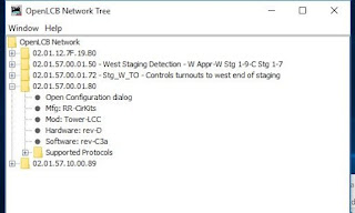
The blog post on configuring a node raised some eyebrows since the nodes come essentially already configured for detection.  I had to configure a bunch of Tortoise stall motor drive outputs, so presenting a step-by-step for configuring those kinds of outputs. For this post, I am using an RR-Cirkits Tower-LCC board with an RR-Cirkits SMD-8 stall motor driver board attached.  As before, everything is done via JMRI Panel Pro.   Open Panel Pro and then the OpenLCB config tool: As before, open the node and click on the Config Dialog: You'll see the info upload from the node.  This is a tower LCC with several points already configured.  We will do point 11: Click on tab Line 11 and, just as before, name the point.  Note that it changes to an orange background to show it was not changed on the node: Click on "Write" and it's in! Now scroll down to the Producer/Consumer options.  The whole discussion about producers and co...

LCC Walkaround Video

One of the hardest things about learning about a new hardware system is to simply understand the parts and how they go together.  Here is an introductory walkaround of the LCC components on the GNW.  In the video, you will see the "hubs" - collections of nodes, nodes, both Tower-LCC and Signal-LCC, how the LCC Power-Point ties in, as well as the USB computer interface.  Also presents a few ideas on how to install the system. Link is   HERE Enjoy!

Let’s Configure a Node – The Beauty of LCC (With a bonus section on connecting LCC to PanelPro)

Image
Recall one of the drivers for trying out LCC was to avoid writing detailed code.   Yes, I ~can~ write code.   But it is not my interest or hobby.   As such, anything that can help me translate what is in my head to implementation on a chip somewhere with as little brain damage as possible is quite welcome in my book.   Additionally I did not want the brains of the layout to live in a PC.   There are days when I just want to come down to the basement, flip on the power switch, and run trains.   And… if I am going to go through the trouble of having signals, I want them to come up and operating properly immediately.   Yea, I know I can set up a PC to boot up, execute the right programs and get running on its own.   Sorta.   It’s just one more piece of equipment and step I just don’t care to deal with.        Anyway…. So a big part of my hesitation of leaping into LCC was the angst associated with programming ...