BLI Critter Sound Install using MRC 1717 Decoder
A bit of a detour here... I was asked by someone on my YouTube channel how I packed sound into a BLI Critter. I didn't take many pix, but enough that hopefully you'll see the basic idea.
To start off with, I used an MRC 1717 decoder. Ya, I know. Not many folks care for the MRC decoders. But the 1717 is super tiny, and since this is a critter with some kind of small displacement engine, I figured it would work out ok (it did).
The OEM decoder is only slightly smaller, which is nice for keeping the cab open looking. I liked that a lot, so one the biggest goals of the install was to retain that look and feel.
So you'll have to take off the shell and remove the cab. Here is what it looks like with the MRC 1717 below:
Because of the short wheelbase and the fact the loco will be doing switching, I wanted to add a "stay alive" capacitor to the DCC circuits on the decoder to let it run over dead spots. I used a 16V 1,000 uF cap. This was small enough to fit up into the top of the cab without a problem. Alas, I did not take a pic of it.
Next is adding a negative power lead from the decoder for attaching the cap. Note: the positive is always the blue or common lighting wire.

Next step was fabricating a suitable speaker enclosure for the "cell phone" or "sugar cube" speaker. These are amazing devices. Super powerful and compact. With the little space, I did not want to make an 'optimum' sized enclosure. Instead, I found some suitable strip styrene that would create a reasonable enclosure but still was small enough to fit and not block the open feel of the cab. Perhaps it's some kind of 'electrical box' overhead.
Note I had to notch the enclosure to work around the light tube and electronics.

Sealing the enclosure was critical. I could not have any air gaps that would 'short circuit' the sound. I found mounting putty works great for applications like this. It seals, stays pliable, and is sticky. Great for sealing against the roof, as well as any gaps that may appear.


Yes, that's right - the "front" of the speaker shoots into the enclosure. The sound actually comes out of the back of the speaker. Easier to seal and works great. Counter-intuitive, I know. But it works!

Painted gray to blend into the cab....

And all put together. I did not get any pix of the reassembly. It was a patience-building process. But is all came together... and it works. Was trying to route the wires in front of the engineer along the frame of the cab, but they kept popping into view. Arg. I figured I would just call it good before the locomotive became a projectile!

Here you can see the speaker. Not totally out of view, but unless you are looking for it, it really does not bother.

Ya, some obstructions; but you can see through the windows to the other side. When running it looks pretty convincing as a reasonably empty cab. Not bad for a loco this small... with sound!

If you have not seen it, here is the link to the video running the unit:
https://www.youtube.com/watch?v=EEMubGOOWyA
Enjoy!
To start off with, I used an MRC 1717 decoder. Ya, I know. Not many folks care for the MRC decoders. But the 1717 is super tiny, and since this is a critter with some kind of small displacement engine, I figured it would work out ok (it did).
The OEM decoder is only slightly smaller, which is nice for keeping the cab open looking. I liked that a lot, so one the biggest goals of the install was to retain that look and feel.
So you'll have to take off the shell and remove the cab. Here is what it looks like with the MRC 1717 below:
 |
| BLI decoder above, with the MRC 1717 decoder below. |
Because of the short wheelbase and the fact the loco will be doing switching, I wanted to add a "stay alive" capacitor to the DCC circuits on the decoder to let it run over dead spots. I used a 16V 1,000 uF cap. This was small enough to fit up into the top of the cab without a problem. Alas, I did not take a pic of it.
Next is adding a negative power lead from the decoder for attaching the cap. Note: the positive is always the blue or common lighting wire.
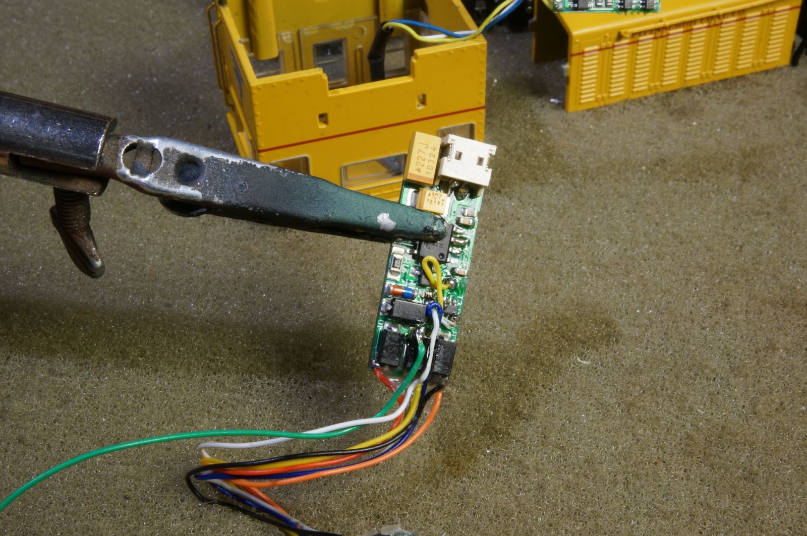
Look closely and you can see where I added the green wire. You can find the proper location by looking for the rectifying diodes, and then sorting out which end of what diodes are the positive and negative rectified power. Reference Marcus Ammann’s excellent page at http://www.members.optusnet.com.au/mainnorth/alive.htm for more details. Good stuff there!
 |
| Note green wire was added for "negative" connection to capacitor. |
Next step was fabricating a suitable speaker enclosure for the "cell phone" or "sugar cube" speaker. These are amazing devices. Super powerful and compact. With the little space, I did not want to make an 'optimum' sized enclosure. Instead, I found some suitable strip styrene that would create a reasonable enclosure but still was small enough to fit and not block the open feel of the cab. Perhaps it's some kind of 'electrical box' overhead.
 |
| Glues 4 sections of strip styrene to the speaker. The roof of the locomotive will form the enclosure. |
Note I had to notch the enclosure to work around the light tube and electronics.

Sealing the enclosure was critical. I could not have any air gaps that would 'short circuit' the sound. I found mounting putty works great for applications like this. It seals, stays pliable, and is sticky. Great for sealing against the roof, as well as any gaps that may appear.


Yes, that's right - the "front" of the speaker shoots into the enclosure. The sound actually comes out of the back of the speaker. Easier to seal and works great. Counter-intuitive, I know. But it works!

Painted gray to blend into the cab....

And all put together. I did not get any pix of the reassembly. It was a patience-building process. But is all came together... and it works. Was trying to route the wires in front of the engineer along the frame of the cab, but they kept popping into view. Arg. I figured I would just call it good before the locomotive became a projectile!

Here you can see the speaker. Not totally out of view, but unless you are looking for it, it really does not bother.

Ya, some obstructions; but you can see through the windows to the other side. When running it looks pretty convincing as a reasonably empty cab. Not bad for a loco this small... with sound!

If you have not seen it, here is the link to the video running the unit:
https://www.youtube.com/watch?v=EEMubGOOWyA
Enjoy!


Comments
Post a Comment